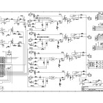
Here’s the code (and schematics) from the AniModule M1xXOR
It might look a little messy 😉 that’s because I haven’t cleaned it up for public consumption. the way it’s going in to your IC is the way I posted it up here.
You can copy/paste directly to your Arduino IDE.
it won’t compile unless you have Paul Stoffregen’s digitalWriteFast Library installed. There’s a little more about this on the Schematics / Code page.
There are pads for a 5 pin header at the bottom right of the ATMEGA328.
Installing a Header here facilitates an ICSP to use upload sketches directly to the Module without having to pull the IC.
From top to bottom the pins connect to the ATMEGA328:
VCC (I’m using +5V)
VSS (GND)
TX
RX
Reset
You can connect directly from an Arduino with the IC removed to program it or use a USB to TTL converter etc.
The VCC is connected to the Modules +5V via a diode so no need to fear for your USB port if you forgot to disconnect your -/+12V EuroRack PSU before you connected your programmer 😉
If you make changes to the code or come up with something interesting to do with the M1xXOR I’d LOVE to hear about it! Please take the time to register and post up in the comments! You can also catch me via email, or PM / Post on Muff’s or Electro Music or the AniModule FaceBook Page.
#include <digitalWriteFast.h>

const int sensorMin = 0;
const int sensorMax = 1024;

int clkIn = 2;
int rstIn = 3;

int prevRange;
boolean clkState;
boolean prevClkState;
boolean rstState;
boolean prevRstState;
int count;
int prevCount;
int range;
int rangeClk;
int rstCnt;

void setup() {
  DDRD = B11110010;  //Set PORTD to output except rx, Clock, Reset

  //Variables for Power ON
  PORTD = PORTD & B00000011;  //Set pins 2 - 7 outputs low
  /*pinModeFast(clkIn, INPUT);
  digitalWriteFast(clkIn, LOW);
  pinModeFast(reset, INPUT);
  digitalWriteFast(reset, LOW);*/

  prevRange = 0;
  clkState = LOW;
  prevClkState = LOW;
  rstState = LOW;
  prevRstState = LOW;
  count = 0;
  prevCount = 0;
  range = 0;
  rangeClk = 0;
  rstCnt = 1;

  Serial.begin(9600);
  }

void loop() {
  clkState = digitalReadFast(clkIn);
  rstState = digitalReadFast(rstIn);
  int sensorReading = analogRead(A1);
    //read incoming voltage

   //
   if (clkState == HIGH){
     if (prevClkState != clkState){
     if (rangeClk < 4) {rangeClk +=1;}
     else {rangeClk = 1;}
     }
   }

   if (rstState == HIGH){
     if (prevRstState != rstState){
       rangeClk = 0;
     }
    }
   range = map(sensorReading, sensorMin, sensorMax, 0, 5);
    //map voltage to range of 5 options
   range += rangeClk;
   if (range > 4){
     range -= 4;
   }

    //for (range=0; range<6; range++){


  Serial.print("range = " );
  Serial.println(range);

  switch (range) {
   case 1:
    PORTD = PORTD | B10000;
    //Pin 4 HIGH
    PORTD = PORTD & B011111;
    //Pin 5 LOW
     break;
   case 2:
    PORTD = PORTD | B100000;
    //Pin 5 HIGH
    PORTD = PORTD & B0101111;
    //Pin 4, 6 LOW
     break;
   case 3:
    PORTD = PORTD | B1000000;
    //Pin 6 HIGH
    PORTD = PORTD & B01001111;
    //Pin 7, 8 LOW
     break;
   case 4:
    PORTD = PORTD | B10000000;
    //Pin 7 HIGH
    PORTD = PORTD & B10001111;
    //Pin 6 LOW
    break;
   default:
    PORTD = PORTD & B00001111;
    //Pin 4, 5, 6, 7 LOW
    break;
   }
   prevClkState = clkState;
   prevRstState = rstState;
}